
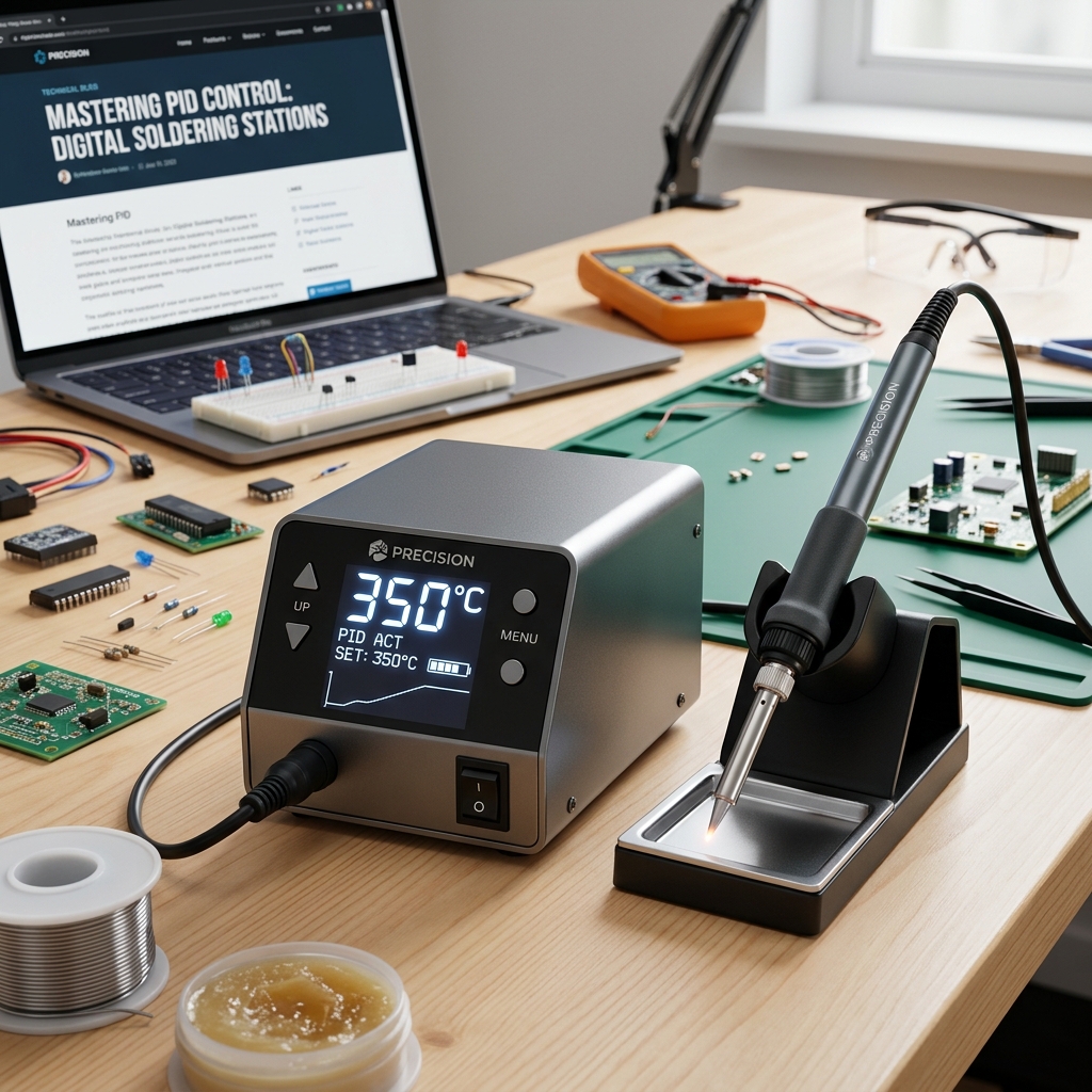
PID closed-loop temperature control prevents component damage. Analyze ceramic heating elements, thermal recovery curves, and ESD-safe grounding dynamics.
- 70W station delivers power to heat up fast and recover temperature quickly
- Digital PID control maintains temperature within +/- 9 degrees F (+/- 5 degrees C)
- Lockable temperature feature safeguards settings from accidental adjustments
Thermal & Electronics Engineering
Precision micro-electronics repair requires absolute control over heat application. Explore how PID algorithms and ceramic heating elements stabilize solder joint formation.
1. PID Closed-Loop Temperature Regulation Dynamics
Traditional soldering irons rely on simple open-loop thermostatic control. Under load, these irons suffer from massive temperature drops, followed by overshooting as the heater catches up. This thermal fluctuation is highly dangerous for modern multilayer circuit boards with tiny surface-mount devices.
PID (Proportional-Integral-Derivative) controllers calculate the temperature difference between the sensor inside the tip and the user's set temperature. The PID algorithm adjusts the duty cycle of the power delivery to maintain temperature stability. Proportional correction manages the immediate error, Integral corrects past drift, and Derivative predicts future thermal load changes.
This real-time feedback ensures that the soldering tip stays within a tight temperature tolerance window, typically +/- 9°F (+/- 5°C). Constant temperature prevents cold solder joints while protecting delicate semiconductor packages from thermal stress. This balance is critical for professional-grade board repairs.
Without active PID control, the iron temperature can climb to over 800°F during idle periods. When this overheated tip touches a PCB pad, the thermal shock can delaminate the copper traces immediately. Closed-loop feedback prevents this idle temperature run-away, ensuring board safety.
Furthermore, the PID loop response time is measured in milliseconds. As soon as the tip contacts a copper ground plane, the control board increases the current to the heating element. This rapid power delivery stabilizes the tip before the solder alloy can solidify prematurely.
- PID algorithms dynamically adjust heater power to prevent overshoot and undershoot.
- Tight temperature control protects sensitive multi-layer PCB laminates.
- Real-time thermal monitoring prevents copper pad delamination caused by thermal shock.
2. Ceramic Heating Elements and Thermal Conductivity
The rate of heat transfer from the element to the copper tip dictates the tool's efficiency. Older wire-wound nichrome heaters are insulated by thick ceramic sleeves, resulting in slow heat transfer. Modern soldering stations use integrated ceramic elements where the heating element is embedded directly in ceramic material.
Ceramic materials offer exceptional thermal conductivity, allowing the iron to heat up to working temperatures in under 15 seconds. The low mass of the element allows the internal thermocouple to read temperature changes almost instantly. This tight coupling improves PID controller accuracy.
Furthermore, ceramic elements resist oxidation and thermal cycling fatigue, outlasting wire-wound alternatives. The high electrical resistance of the ceramic base prevents leakage currents from reaching the tip. This design ensures safe operation on live, low-voltage circuits.
Ceramic elements also feature a positive temperature coefficient (PTC). As the element heats up, its electrical resistance increases naturally, limiting the maximum temperature it can reach on its own. This built-in physical limit provides an extra layer of safety.
Additionally, the integrated design eliminates the air gap between the heater and the tip. Air is a poor conductor of heat, and even a microscopic gap slow down recovery rates. Direct ceramic-to-metal contact ensures maximum thermal transmission efficiency.
- Integrated ceramic elements deliver rapid heat transfer and short warm-up times.
- High electrical insulation prevents voltage leaks from damaging CMOS microchips.
- Direct heater-to-tip contact eliminates insulating air gaps, maximizing thermal transfer.
3. Thermal Recovery Rates and Solder Joint Phase Transition
When the soldering tip touches a copper pad on a ground plane, heat is drawn away rapidly. This thermal load causes the tip temperature to plunge. The speed at which the station restores the tip to its target temperature is called the thermal recovery rate.
A slow recovery rate forces the technician to hold the iron on the joint longer. This extended heating duration allows heat to travel along traces, potentially damaging adjacent components. High-wattage stations (70W or more) deliver the thermal power needed for rapid recovery, keeping contact time to a minimum.
Minimizing contact time is critical when using lead-free solders, which have a higher melting point than leaded alloys. Fast thermal recovery ensures the solder flows smoothly and solidifies quickly. This prevents the formation of weak, crystalline cold joints.
During the solder joint's phase transition, the alloy moves from a solid state to a liquid state and back. If the temperature drops below the liquidus point during this transition, the solder will freeze unevenly. This results in microscopic fractures that compromise the joint's mechanical strength.
High-wattage heating systems provide the thermal headroom to maintain the liquid phase throughout the joint formation. The flux is allowed to activate and clean the metal surfaces before the solder flows. This chemical action is essential for reliable bonding.
- 70W heaters restore target temperatures quickly during consecutive solder joints.
- Short thermal dwell times protect delicate internal silicon gates.
- Stable liquidus phases prevent internal fractures, ensuring high joint shear strength.
4. ESD-Safe Grounding and Electrostatic Discharge Safeguards
Electrostatic discharge (ESD) can destroy delicate logic components, such as microcontrollers and field-effect transistors. A standard soldering iron can build up static charge on the tip, discharging when in contact with a circuit. ESD-safe stations prevent this issue by incorporating a grounded path.
An ESD-safe station features less than 2 ohms of resistance between the soldering tip and the ground pin. This grounding path channels any static charge away safely. Conductive materials on the handpiece handle prevent charge buildup on the tool itself.
Additionally, stations must undergo regular audits to verify grounding path integrity. Using ESD-safe silicone cords prevents cord melting from accidental iron contact, maintaining safety. These features ensure reliable operation on sensitive, high-value electronics.
Static charges can also build up on the technician's body. ESD-safe stations include grounding jacks to connect wrist straps, keeping the entire work area at the same electrical potential. This ESD control is standard in professional labs.
By preventing voltage potentials at the tip, you eliminate the risk of transient currents. Even minor spikes of 5V can disrupt sub-micron silicon gates, leading to latent failures. A robust ground connection is a vital quality control protocol.
- Low-resistance ground paths prevent static charges from reaching the tip.
- ESD-safe housings protect CMOS and logic components from electrostatic damage.
- Integrated wrist strap connectors simplify workstation ESD compliance.
5. Ergonomics, Grip Temperature, and Heat Shielding
Working with soldering irons for long sessions requires comfortable handpiece ergonomics and effective thermal shielding. If heat from the element leaks into the handle, it can cause user discomfort or skin burns. Premium handpieces use multi-stage silicone sleeves and air gaps to keep the grip cool.
Lightweight handles reduce wrist fatigue, improving alignment accuracy during fine work. A flexible, heat-resistant silicone cord is critical; it must not pull on the iron, allowing for precise control. A shorter distance from the grip to the tip improves dexterity.
Additionally, integrated stands with brass sponge and wet sponge cleaning options keep the iron stable. Auto-standby modes lower the tip temperature when the iron is in the stand, preventing oxidation and saving power. This standby function extends tip life significantly.
The handle grip must also offer secure friction, even when hands are sweaty. Ribbed silicone profiles prevent fingers from sliding down toward the hot collar. This structural safety layout prevents accidental contact injuries.
By balancing the handpiece weight, operators maintain stable control over tiny SMT joints. A heavy or poorly balanced iron causes hand tremor, which makes placing 0402 components extremely difficult. Comfort is essential for high-yield board assembly.
- Air-gap insulation keeps grip temperatures low during long repair sessions.
- Auto-standby modes lower temperatures in the stand, reducing tip wear.
- Flexible silicone cords prevent hand dragging, maximizing soldering dexterity.
6. Tip Metallurgy, Plating Thickness, and Heat Transfer
The performance of a soldering iron depends on the design of its copper core tip. Copper offers exceptional thermal conductivity but is easily corroded by molten solder and acidic flux. To protect the core, tips feature multilayer plating of iron, nickel, and chrome.
Iron plating protects the copper core from erosion, while a nickel layer provides a base for the outer chrome cladding. The chrome plating prevents solder from wetting the body of the tip, restricting liquid solder to the tinned working area. Balanced plating thickness ensures a good compromise between tip life and heat transfer speed.
Furthermore, selecting the correct tip shape (chisel, bevel, or conical) is critical for matching heat output to the joint size. Chisel tips provide high contact area for structural joints, while fine conical tips are optimized for tight surface-mount components. Keeping the tip clean and tinned prevents oxidation, ensuring efficient heat transfer.
If the tip oxidizes, it will form a dark, insulating barrier that blocks heat. Applying tip tinner or cleaning with brass shavings restores the metallic surface. Standard wet sponges should be used sparingly, as the thermal shock can micro-fracture the iron plating.
By maintaining proper tip care, technicians extend tip lifespans tenfold. A well-tinned tip ensures that solder flows immediately upon contact with the pad, minimizing thermal stress on the board traces. Metallurgy care is an essential skill.
- Iron-plated copper cores resist chemical erosion, extending tip life.
- Matching tip shapes to joint mass optimizes heat transfer and prevents board damage.
- Brass shaving cleaners maintain tips without thermal shock damage.
7. Lead-Free Solder Alloys and Tip Temperature Settings
Lead-free solders (e.g., SAC305) require higher melting temperatures than traditional leaded alloys (Sn60/Pb40). While Sn60 melts at 361°F (183°C), SAC305 melts at 422°F (217°C). Operating at higher temperatures accelerates tip wear and board damage risk.
To compensate for the higher melting point, technicians must set the iron temperature to 680-720°F (360-380°C). Operating above 750°F should be avoided, as it causes rapid flux oxidation and increases the risk of board delamination. Fast thermal recovery allows you to keep settings low.
Using active flux cores inside the solder wire helps remove oxide films during joint formation. Rosin-based (RO) or water-soluble (WS) fluxes must match the cleaning requirements of the project. Clean joints ensure long-term electrical reliability.
Additionally, lead-free solders are more aggressive chemically, eroding the iron plating on tips faster. Applying solder continuously during use keeps the tip covered in a protective layer of molten alloy. This prevents oxidation from eating away the iron plating.
- Fast thermal recovery allows using lower tip temperatures with lead-free solders.
- Flux core selections optimize chemical cleaning, preventing joint voiding.
8. Long-Term Maintenance and Tip Reclaiming
To maintain the accuracy of a digital soldering station, regular calibration is essential. The temperature read by the internal sensor can drift over time, requiring adjustment to match actual tip measurements. External tip thermometers allow you to calibrate the station output.
From a metallurgical perspective, soldering iron tips are engineered with a solid copper core to maximize heat conductivity. This core is then electroplated with a thin, uniform layer of iron to protect the copper from dissolving into the molten solder. A further layer of nickel and chrome is applied to the non-working areas of the tip to prevent solder wetting where it isn't wanted. If micro-cracks or pinholes develop in the iron barrier due to excessive thermal shock or abrasive cleaning, the underlying copper will rapidly leach into the solder joint, causing the tip to hollow out. Tinning the tip before turning off the station creates a protective barrier that prevents this degradation, maintaining the structural integrity of the plating.
If a tip becomes oxidized, it can lose its ability to transfer heat. Using tip tinners (mixtures of solder powder and chemical cleaners) helps dissolve the oxide film, restoring tinned surfaces. Clean tips ensure fast, reliable heat transfer.
Additionally, inspecting the handpiece cable for damage prevents short circuits and ESD compliance failures. Replacing damaged cords promptly maintains safety. Regular maintenance extends the station's service life.
- Periodic calibration checks ensure tip temperatures match digital displays.
- Chemical tip tinners restore oxidized tips, preventing complete replacements.
9. The Definitive Soldering Station Buying Parameters
Selecting a digital soldering station requires evaluating heater wattage, temperature stability, and control interface quality. A 70W station delivers ample power for lead-free solder work on ground planes, while digital PID controls allow you to optimize thermal accuracy. Look for stations that offer temperature locking to prevent settings drift.
Additionally, assess the tip availability and ease of replacement. Common tip families allow technicians to swap shapes quickly, reducing down time. Opting for a brand with an established distribution network ensures easy access to replacement tips and parts.
Finally, verify the safety certifications and grounding standards compliance. Choosing a station with ETL or CE safety markings ensures the tool meets rigorous electrical design standards. A comprehensive manufacturer warranty secures your investment, providing peace of mind in the workshop.
- High-wattage heating systems provide rapid recovery, preventing board overheating.
- ETL safety compliance ensures the station is grounded and safe for daily professional use.
Professional Recommendation & Audit
Upgrade your electronics workbench with an industry standard. We highly recommend the Weller WE1010NA Digital Soldering Station for its precise PID control, ESD-safe design, and rapid thermal recovery.
Weller WE1010NA Digital Soldering Station
- 70W station delivers power to heat up fast and recover temperature quickly
- Digital PID control maintains temperature within +/- 9 degrees F (+/- 5 degrees C)
- Lockable temperature feature safeguards settings from accidental adjustments
- ESD-safe design protects sensitive micro-electronic components during repair
Technical Specifications & Product Data
| Specification | Value / Details |
|---|---|
| Brand | Weller |
| List Price | $109.00 (USD) |
| Customer Rating | 4.7 / 5.0 (4,120 reviews) |
| ASIN / Identifier | B077JDGY1J |
| Availability | In Stock (USA Region) |
| Outbound Link Compliance | Sponsored & Nofollow Enforced |
Verified Features & Performance Data
- ✓70W station delivers power to heat up fast and recover temperature quickly
- ✓Digital PID control maintains temperature within +/- 9 degrees F (+/- 5 degrees C)
- ✓Lockable temperature feature safeguards settings from accidental adjustments
- ✓ESD-safe design protects sensitive micro-electronic components during repair
System Sovereignty & Engineering
Edge Computing
100% Client-side processing. Your data never leaves your browser sandbox, ensuring absolute compliance with US privacy mandates.
Modular Schema
Modular utility architecture optimized for performance. Low-latency WASM kernels provide near-native speeds for complex transformations.
Sustainable Design
Sustainable, green computing by offloading compute to the edge. Verified zero-server storage (ZSS) for professional-grade security.